Tech Talk
AeroVane II & III
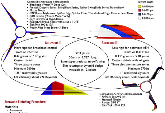
Aerovane is the first and only vane to employ Airfoil Technology (US Patent: 8,105,189) for archery arrows. Aerovane does not look like and does not work like traditional vanes. It it is not flat, it is not smooth, and it does not use drag. Read on to learn what it is instead and why.
Drag versus Circular Lift
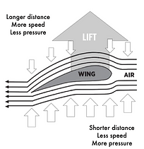
Unlike every other vane on the market, Aerovane does not use drag. Flight fundamentally is a process of deceleration. This is due to drag. Without drag (and gravity, of course,) objects in flight would stay in flight forever. Drag is an opposing force and it only increases as speed does, to the point that it wastes energy. Aerovanes, however, use lift instead of drag. Specifically, they utilize Airfoils Technology to maintain energy throughout flight. By definition, airfoils are structures that’s shape takes advantage of something called Bernoulli’s Principle. Bernoulli’s Principle states that an increase of speed occurs simultaneously to a decrease of pressure. But what does that mean and why does it matter? There is air flowing over and under the structure named “wing.” Due to the wing’s shape, the air above must travel farther and therefore faster, exerting less pressure. The opposite is the case for the air below—it must travel a shorter distance and therefore can travel slower, but as a consequence exerts more pressure. This imbalance in pressure creates lift. But that’s just one wing. For arrows, usually, there are three vanes and therefore, if Aerovane equipped, three wings. And together, the three separate lift forces create circular lift. Further, as an aftereffect of our reliance on circular lift instead of drag, the crosswind signature of an Aerovane equipped arrow is exponentially smaller than usual. High crosswinds have minimum effect on arrow trajectory.
Custom arrows


Arrow Flight
The Null Point
The null point or node (red dot) is the unique segment of an arrow where no vertical or horizontal movement occurs at initial launch.
But how do you find it, why should you find it and what do you do with it after you find it?
-
Loosely hold a complete arrow by its nock end and knock it on a hard surface from a few inches away until you hear a solid shift
in tone. The arrow should also not bounce when the node is located.
-
Your arrow rest should match up with the node when you pull back. That way, there will be a minimal chance of your arrow
skewing away from true center at initial launch.
-
To take full advantage of your arrow’s inherited null point, use it when tuning your archery setup today.

Oscillation & Its Resulting Motions
Consider this—your arrow oscillates during flight. And during this oscillation process, a lot of energy is lost. This is because your shot arrow, as any object with energy, needs to reach an equilibrium.
Pictured at the top right, the ideal arrow motion scenario (and unfortunately the one most believe to always be the case) is a linear flex [0, left] through a center point where the first (red dot) and second dynamic bend (blue dot) are 180 degrees from one another. This would result in the expense of the minimum amount of elastic energy lost. Further, even if it was to flex in a parabolic motion [0, right] the true center of the shaft would always be maintained.
Unfortunately however, such a scenario is “ideal” and even a perfectly extruded aluminum arrow made with truly homogeneous material and a completely linear spine would not move in this fashion. To reach that “equilibrium,” an arrow, no matter how “perfect,” will sporadically flex and bend during flight.
Exactly how sporadic an arrow’s movement is during oscillation depends how its three central resulting motions manifest and interact with one another. Note also that they all happen simultaneously.

1. Actual linear flex occurs indeed through a first (red dot) and a second dynamic bend (blue dot), but not 180 degrees from one another. Instead, common pairings will be at something like twelve and four o’clock (120 degrees) or twelve and seven o’clock (-150 degrees). This motion results in the deformation of the center of the arrow from round to elliptical and many times, off-center elliptical.
2. Torsion, or opposite circular longitudinal flex occurs when an arrow is flexing linearly at both ends in two opposite directions. This motion is a byproduct of the previous motion, actual linear flex.
3. Finally, as another byproduct of actual linear flex, an off-center rotation occurs. This rota- tion is due specifically to the aforementioned deformation of the round shape of the shaft and follows a parabolic path.
ACS Version 1.0 (Firenock AeroConcept System)
The AeroConcept System (ACS) involves four elements, three of which are familiar to most—an arrow shaft, an insert, and a point. The last element of the ACS, unique to Firenock, is a “Carbon Inner Tube”. This tube, as suggested, is made of carbon and is intended to sit within an arrow shaft. Specifically, its designed for installation with an AeroInsert-H to create one large insert unit. The question still remains however, why include this Carbon Inner Tube? Well, the AeroConcept System, via this extra element, will not only strengthen your arrow’s front end, but also gives your arrow a variable spine (i.e. spine at the front and at the back are different). The first effect’s cause is obvious. By adding—i.e. gluing with the intention of melding—a new, smaller carbon tube into your shaft, the overall wall thickness increases at the front, stiffening and generally reinforcing it. The reason for the second effect, the variable spine, is a bit trickier. To explain, first recall the oscillation cycle of a standard arrow from the AeroFlight 101 spread. Now, realize that due to the addition of the CTI, the spine is higher near the front than everywhere else. This distinction means that the radius of that oscillation is shortened significantly. And due to that shorter radius, the cycle of oscillation is dampened—in fact, harmonically dampened (US Patent: 9,395,166). Your arrow stops flexing significantly faster and thus begins flying flat faster. With your arrow equipped with the AeroConcept System and Aerovane II or III, it can even enter a gyro spin.

ACS Version 2.0 (Firenock AeroConcept System)
The AeroConcept System 2.0 (ACS2), introduced in 2018, involves all four elements of the ACS but with the supplement of another Carbon Inner Tube at the back of an arrow behind the nock or Firenock lighted nock system (US Patent: 10,232,581). To understand the benefits of the ACS2, just imagine those of the ACS and then amplify them by 30-40%. The aforementioned radius of oscillation is even smaller (see illustration below), allowing for further energy retention. An arrow equipped with ACS2 will fly yet flatter and therefore with an even higher POI (point of impact).

